Ladder
Logic Programming Tutorial STEP 5 ![]()
![]()
Ladder
Logic Programming Tutorial STEP 5 |
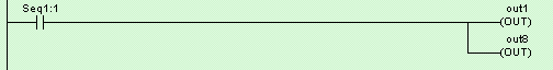
Circuits #3 to #6 are similar to one another. They make use of the Sequencer to turn on the Outputs 1 to 8 to create a pattern of "running lights" when executed. The label "Seq1:1" of the contact in Circuit #3 represents Step #1 of Sequencer 1. Remember that each sequencer can have up to 32 steps (Step #0 to 31), with each step individually accessible as a contact. A normally-open contact "Seq1:1" will be closed whenever the step counter of Sequencer 1 reaches number 1. Likewise a normally-closed contact "Seq5:20" will be opened when the step counter of Sequencer 5 reaches number 20.
We have thus far been creating ladder circuits only by clicking on the ladder icons. A short-cut method of choosing elements to be created without using the mouse does exist. Observe the icon carefully and you will notice a small numeral at the lower right hand corner of each icon which correspond to the shortcut key. You may wish to try this short-cut for the remaining part of Circuit #3. Press the <7> key and the Output table will immediately pop up for selection of a coil. Pick "Out1" from the "Output" table and the "Out1" coil will be connected.
Circuits #4, 5 and 6 are very similar to Circuit #3 and you shouldn't have problem creating them. Complete these circuits and we are ready for some interesting simulation exercises. When you have created all the circuits, press <Enter> key or <ESC> key at the last blank circuit to end "Ladder Edit" mode.
We can make our program more comprehensive to other users by utilizing the "Comments" feature of TRiLOGI. Open the "Circuit" menu and select "Insert Comment". A comment editor window will be opened up to allow you to add your comments to any part of the circuit. When you are done with your comments, just press <ESC> key or close the comment editor window and the comments you just entered will be inserted between the circuits. Each comment occupies a circuit position and there is no limit to the number of lines a comment circuit may have.( However, if you wish to keep data file compatibility with the old TRiLOGI Version 4.x you should limit the comment to no more than 4 lines per comment and each line should contain no more than 70 characters.)
A comment circuit may be moved around or deleted just like any other ladder circuits. If you wish to edit the comment, just double-click on it or press the <Spacebar> to open up the comment editor window. You can use the normal text editing keys such as left, right, up, down cursor keys, and <Ctrl-Left>, <Ctrl-Right>, <Del> and <Backspace> keys for editing the comment text.
Back to Step 4 ![]()
![]() Goto Step 6
Goto Step 6