Ladder
Logic Programming Tutorial STEP 4 ![]()
![]()
Ladder
Logic Programming Tutorial STEP 4 |
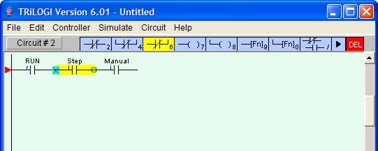
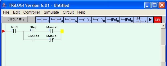
We will now create Circuit #2 as shown below.
Follow the steps listed in STEP 3 to create the following circuit fragment:
We want to enclose the two series contacts "Step" and Manual" with a parallel branch that contains two elements. First, we will create the branch for the N.C. "Manual" contact.
Click on the element "Step" to
highlight it. Then right-click on the ![]() icon to create a N.C. parallel circuit that encloses both the "Step"
and the "Manual" contacts. A cross will appear at the left hand end of the
"Step" contact, indicating that this is the starting location of the parallel
circuit. You should now click on the "Manual" contact to select the ending
location for the parallel circuit. The yellow highlight bar will be positioned at
"Manual" contact now.
icon to create a N.C. parallel circuit that encloses both the "Step"
and the "Manual" contacts. A cross will appear at the left hand end of the
"Step" contact, indicating that this is the starting location of the parallel
circuit. You should now click on the "Manual" contact to select the ending
location for the parallel circuit. The yellow highlight bar will be positioned at
"Manual" contact now.
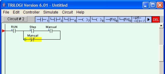
You will notice that the ![]() icon has now changed into a yellow
color N.C. contact
icon has now changed into a yellow
color N.C. contact ![]() with an opposite connection arm. You
should now click on the
with an opposite connection arm. You
should now click on the ![]() symbol to close the parallel branch.
(One possible short-cut method is to double-click at the ending location to close the
branch).
symbol to close the parallel branch.
(One possible short-cut method is to double-click at the ending location to close the
branch).
As usual an I/O table will be opened for you to select the I/O. For now, select the
"Manual" label from the "input" table to create the following circuit:
Note: The "Special Bit" table comprises some clock pulses and some other special purpose bits. These include the eight built-in clock pulses in the system with periods ranging from 0.01s to 1 minute. Built-in clock pulses are useful if you need a time base to create, for example a "flashing light". A contact such as "Clk:0.1s" will automatically turn itself ON for 0.05s and then OFF for another 0.05s and then ON again, resulting in a series of clock pulses of period = 0.1 second.
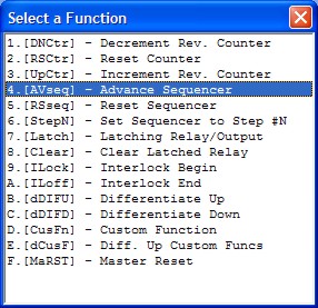
Now, click on the ![]() icon to insert a special function coil. A popup menu
will appear for you to select the desired special function. Click on the item
"4.[AVseq]-Advance Sequencer" to insert the Advance Sequencer function [AVseq].
icon to insert a special function coil. A popup menu
will appear for you to select the desired special function. Click on the item
"4.[AVseq]-Advance Sequencer" to insert the Advance Sequencer function [AVseq].
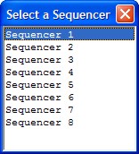
When prompted, select Sequencer 1. This function will increment the step counter of Sequencer #1 each time its execution condition goes from OFF to ON.
Again, remember to press the <Enter> key to complete Circuit #2
Back to Step 3 ![]()
![]() Go To Step 5
Go To Step 5