Ladder Logic Programming Tutorial STEP 3
![]()
![]()
Ladder Logic Programming Tutorial STEP 3
|
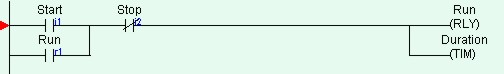
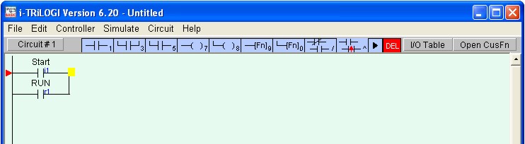
We are ready to create Circuit #1 as shown below:
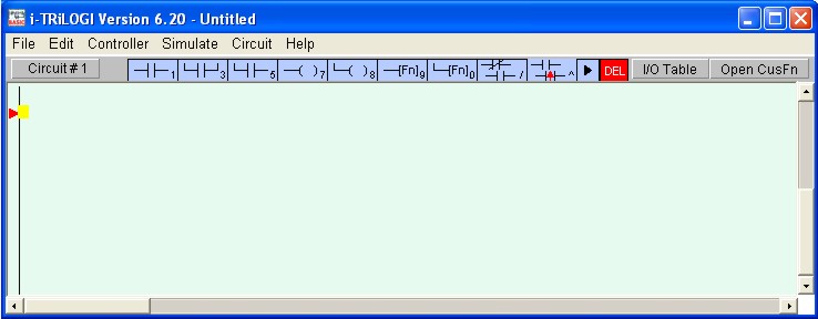
With the circuit pointer (red color triangle) at Circuit #1, press the <Spacebar> to enter the "Ladder Edit" mode. You can also enter the circuit edit mode by double clicking at Circuit #1.
Once you enter the "Ladder Edit" mode, a row of ladder icons appear along the top of the main i-TRiLOGI window just below the pull down menu. The following is a description of each item. A yellow color highlight bar, which you can move to select an element in the ladder circuit, will appear.

<1> - Left click to insert a normally-open series contact.
<2> - Right click to insert a normally-closed series contact.<3> - Left click to insert a N.O. parallel contact to highlighted element
<4> - Right click to insert a N.C. parallel contact to highlighted element<5> - Left click to insert a N.O. parallel contact to enclose one or more elements.
<6> - Right click to insert a N.C. parallel contact to enclose one or more elements.<7> - Insert a normal coil which may be an output, relay, timer or counter. <8> - Insert a parallel output coil (not an entire branch) to the current coil. <9> - Insert a special function coil which includes execution of CusFn <0> - Insert a parallel special function coil to the current coil. </> - Invert the element from N.O. to N.C. or from N.C. to N.O. <^> - Convert the element to a rising-edge triggered contact (one shot) Click to move the highlight bar to the right (same effect as pressing the right arrow key).
This can be used to move the cursor to a junction which cannot be selected by mouse click.Double-click to delete a highlighted element. This acts as a safety against mistake.
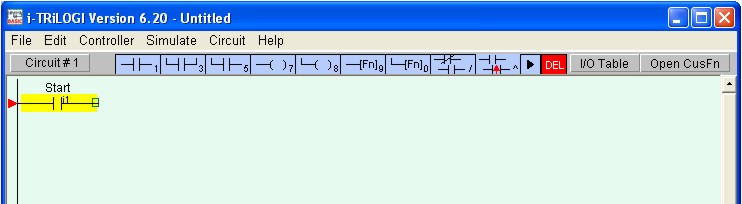
Now insert the first element by left-clicking on the ![]() icon. The
icon will change to a bright yellow color to show you the element type that you are
creating. At the same time, an I/O table should appear on the screen with a light
beige-color background instead of the normal light blue background. The I/O table now acts
like a pop-up menu for you to pick any of the pre-defined label names for this
contact.
icon. The
icon will change to a bright yellow color to show you the element type that you are
creating. At the same time, an I/O table should appear on the screen with a light
beige-color background instead of the normal light blue background. The I/O table now acts
like a pop-up menu for you to pick any of the pre-defined label names for this
contact.
Note: In i-TRiLOGI version 6.x, if you pick any undefined I/O you will be prompted to enter the label name and what you entered will automatically be updated in the I/O table.
The contents in the table are not normally meant to be edited at this moment . Scroll to the "Input" table and click on the label name "Start" and a normally-open contact will be created at Circuit #1.
If you observe the highlight bar carefully, you will notice a dark green color square at the right end of the highlight. This indicates the insertion location where a series contact will be attached. You can change the insertion location to the left or the right of the highlight bar by pressing the <SHIFT> key or <TAB> key (Note: <TAB> key only works on JRE 1.3.1 or earlier. It does not work on JRE 1.4.x)
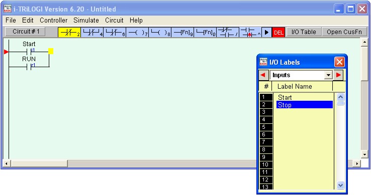
Next, create the contact "RUN" which is parallel to the
"Start" contact by left-clicking on the ![]() icon. The I/O table will appear again.
Scroll to the "Relay" table and select the "RUN" relay.
icon. The I/O table will appear again.
Scroll to the "Relay" table and select the "RUN" relay.
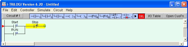
To insert the normally-closed "Stop" contact in series with
the "Start" and "Run" contacts, you need to move the highlight bar to
the junction of the "Start" and "Run" contact. First click on the
"Start" contact to select it. Then click on the ![]() icon to
move the highlight bar to the junction, as follow:
icon to
move the highlight bar to the junction, as follow:
Note: The highlight bar will move to the junction if you click on the dark green insertion point on the "Start" contact.
Next, right-click on the ![]() icon. It will change into yellow color
normally-closed contact as shown in the above diagram. You are now inserting a
normally-closed series contact at the location of the highlight bar. Pick the
"Stop" label from the "Input" table to add the series contact.
icon. It will change into yellow color
normally-closed contact as shown in the above diagram. You are now inserting a
normally-closed series contact at the location of the highlight bar. Pick the
"Stop" label from the "Input" table to add the series contact.
We will now connect a relay coil "Run" to the right of the
"Stop" contact. Click on the ![]() icon to insert the coil. Select "RUN" label
from the "Relay" table. Remember that an input can never be used as a coil.
Fortunately, i-TRiLOGI is smart enough not to call up the "Inputs" table when
you are connecting a coil, to avoid unintentional errors.
icon to insert the coil. Select "RUN" label
from the "Relay" table. Remember that an input can never be used as a coil.
Fortunately, i-TRiLOGI is smart enough not to call up the "Inputs" table when
you are connecting a coil, to avoid unintentional errors.
Notice that the coil symbol ---(RLY) indicates that this is a relay coil, which is helpful in identifying the function of the coil. i-TRiLOGI automatically places the coil at the extreme right end of the screen and completes the connection with an extended wire.
Right below the relay coil is a parallel timer coil with label name
"Duration". To create this coil, click on the ![]() icon. This
allows you to connect a parallel coil to the existing coil. The "I/O" table will
pop up for selection again. Since we want to choose a timer, scroll to the
"Timer" table and pick the first timer with the label "Duration" to
complete the circuit.
icon. This
allows you to connect a parallel coil to the existing coil. The "I/O" table will
pop up for selection again. Since we want to choose a timer, scroll to the
"Timer" table and pick the first timer with the label "Duration" to
complete the circuit.
Press the <Enter> key once to complete Circuit #1
Congratulation! You have just successfully created you very own ladder logic circuit. It is that simple! It may be a good time to save your program now by pressing <CTRL-S> key or select "Save" from the "File" menu and give a file name for you new program.
Back To Step 2 ![]()
![]() Go To Step 4
Go To Step 4