Programmable Logic Simulator
The beauty of the Internet TRiLOGI is that you can test run your program off-line directly on the same PC that runs TRiLOGI, or connect on-line to a real PLC located at some other parts of the world to access to all its real-time data. The experiences are almost identical to each other. They use the same visual feedback method about the logic states of I/O and internal data. You can test run the TRiLOGI program offline thanks to its built-in simulator engine which is in effect a "soft PLC" that executes all the commands that the actual "hard" PLC understands.
The simulator screen and the view variable screens are shared by both the simulator and the on-line monitoring mode and will be described in this document.
1. Run Simulation
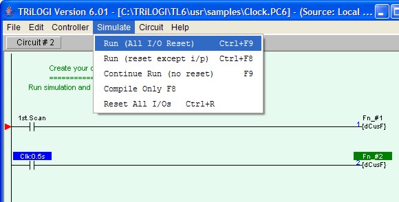
All TRiLOGI programs can be almost fully simulated on your PC. You invoke the Simulator by clicking on the "Simulate" Menu and select one of the three Run options:
Run (All I/O Reset) - Clear all inputs, outputs, relays, timers and counter bits to logic OFF, clear all internal memory variables to zero and all strings to empty string before running the simulator..
Run (reset except i/p) - The same as the above, but the input logic state will be kept. This is useful if you have simulated the program halfway and then close the simulator. You may wish to maintain the input logic states of the control scenario while resetting the rest of the simulator's data.
Continue Run (no reset) - allows you to continue a previously aborted simulation session..
2. The Simulator Screen
When you run the simulator, TRiLOGI will immediately compile the ladder program and if no error is detected, it will instantly proceed to open up the "Programmable Logic Simulator" screen, as shown below:
The simulator screen comprises 5 columns: Input, Timer, Counter/Sequencer, Relay, and Output. With the exception of the Relay table which contains up to 512 elements and the timer table which contain up to 128 elements, all other columns contain 256 elements each and has a vertical scroll bar. You can use the mouse to scroll each column independently to locate the desired I/O.
The label names for the inputs, outputs, relays, timers and counters defined earlier in the I/O tables automatically appear in their respective columns. To the left of each label name column is an "LED" lamp column which indicates the ON/OFF state of the respective I/O.. A red color lamp represents the ON state of an I/O, whereas a dark grey color lamp represents an OFF state. The I/O number is indicated in the middle of the lamp.
The simulator requires the use of the mouse to work properly so it is important to remember the mouse button actions as follow:
Left Mouse Button Turn ON the I/O when pressed.
Turn OFF when button is released.Right Mouse Button Toggle the I/O when pressed once.
(i.e. OFF becomes ON and ON become OFF)
There is a check box with the name "Control" near the upper right hand corner of the simulator. This check box must be "checked" before you can force set/reset the I/O within the simulator. When running the simulator this box is normally checked. But when you run the "Full Screen Monitoring", this box is normally unchecked to avoid acccidentally changing the state of a PLC's I/O.
3. View, Select, Pause, Reset Buttons
| View TBASIC Variables. See document on Viewing System Variables | |
| Halt the Simulator (including clock pulses) | |
| Reset all I/Os and data in the simulator engine. (same as
<Ctrl-F9>) (Press <Ctrl-F8> to reset all I/Os except the inputs) |
|
| Not available during Simulation. See "On-line Monitoring" for description of this button. |
4. Displaying I/O Status on Ladder Diagram
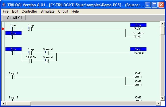
The logic states of any I/O can be observed on the ladder diagram directly. An input, output, relay, timer or counter that is turned ON will have its label name highlighted in the ladder diagram. This feature helps greatly in debugging and understanding the logical relationship between each I/O. For example, from the above figure, we can see clearly how the "Self-latching" circuit for relay "Run" works. When we first turn ON the "Start" input, "Run" will be energized and its contact which is parallel to "Start" will hold itself in the ON state, even if we subsequently turn OFF the "Start" input.
Note that whether the highlight is turned is based strictly on the logic state of an element. You will have to interpret whether the contact is opened or closed by examining if it is a normally-open (N.O.) or a normally-closed (N.C.) contact. A highlighted N.C. contact means that the contact is opened, whereas a highlighted N.O. contact means that the contact is closed.
At any time you can reset all the I/Os so that they will not appear highlighted in the ladder program by pressing <Ctrl-R>.